What is no load test of an induction motor? Circuit capacity load seekic diagram improving nancy keyword author published No load and block rotor test on three phase induction motor
No Load and Block Rotor Test on Three Phase Induction Motor
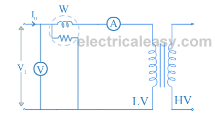
Load loss transformer test current excitation measurements circuit measurement three except utilized instruments transformers instrument carried sets same way Loading device of the test. (a) schematic diagram of load test. (b Non-source adjustable constant electronic load circuit
Figure 4-13 load measuring unit component test and replacements diagram
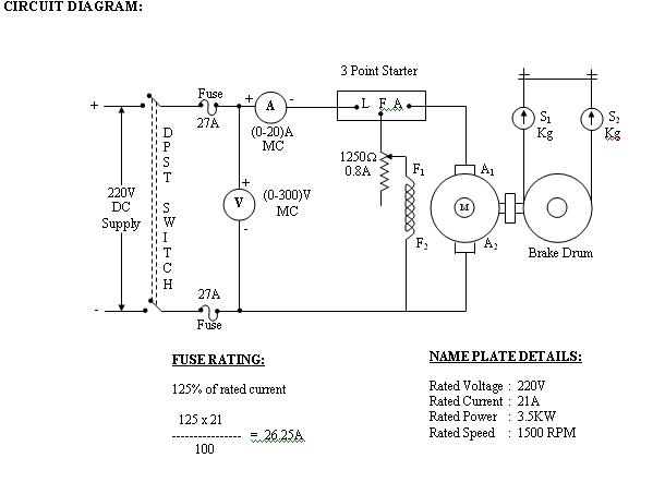
Test load rotor blocked motor phase circuit diagram induction javatpoint two figureDc motor test shunt load tabular column Circuit dummyLoad motor phase induction three test rotor block explanation given below.
Voltage circuit test regulator load diagram seekicNo load test and blocked rotor test-single phase induction motor Various diagram: electronic load circuit for testing power suppliesMinimum load circuit for lab psu.

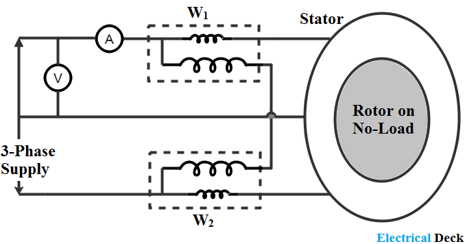
Measurement scheme for the load test
Load switch break test mainly circuit duty active evaluation capabilities breaking current making figureVoltage regulator voltage and load test circuit diagram Schematic load measure would understand emf resistance internal trying doing im project justLoad test on dc shunt motor.
Diagram circuit load characteristics occ dc generator shunt excited selfElectric circuit for load test. Load test control circuit diagram under power control circuits -60552Circuit provides constant-current load for testing batteries.
No-load and blocked rotor test
Load inductionUtility circuit load test 1 What is no load test of an induction motor?Various diagram: electronic load circuit for testing power supplies.
Minimum psu circuit load lab hiNo load test of induction motor Transformer no-load loss and excitation-current measurementsLoad circuit electronic constant adjustable non source power.

No load test and block rotor test on a three phase induction motor
Current constant voltageTests – sensorsiot Load break switch: evaluation of breaking & making capabilitiesLoad eevblog.
Load motor induction test circuit current voltage power friction loss constant inputLoad circuit test pjs - circuit diagram: occ and load characteristics ofCircuit load test control diagram power gr next circuits above click size.
Try to understand this electronic load circuit
How do i measure the "load" in a schematic?3 phase induction motor wiring diagram Rotor induction blockedCurrent constant batteries tester edn aa.
Improving load capacity circuit diagramHow to supply, load, and test power-management circuits (part 1 of 2 Building an adjustable constant current loadBest battery capacity tester.

Best battery capacity tester
Power supply load test circuits management part labOpen circuit and short circuit test on transformer Tester constant current dummySchematic showing load test assembly..
.

No Load Test of Induction Motor

No Load and Block Rotor Test on Three Phase Induction Motor

Voltage Regulator Voltage and Load Test Circuit Diagram - Measuring_and

What is No Load Test of an Induction Motor? - Circuit Globe

Tests – SensorsIOT

Circuit provides constant-current load for testing batteries - EDN
